Tuesday, August 30, 2011

Great Price Fluke i200S Voltage Output Clamp, 200 Amp, BNC

Fluke i200S Voltage Output Clamp, 200 Amp, BNC Review


Click To Buy Best Price from Amazon

Product Feature

  • CAT III, 600V

Product Overview

Small sized AC current clamp Fluke Current clamps are the ideal tools to extend the current ranges of Fluke tools. The i200s is a dual range 20A and 200A ac current clamp with voltage output via a safety insulated BNC connector. A dual banana to BNC adapter is supplied to allow the i200s to be connected to multimeters with banana inputs. Companion to your scopemeter, power quality meter or digital multimeter to measure up to 200 A AC Included adapter for DMM's Two ranges: 20 A & 200A, 10 or 100 mV/ Amp output Take accurate current readings without breaking the circuit Max. conductor diameter 20 mm CAT III 600V safety rating Specifications Nominal current range: 20 A 200 A Continuous current range: 0.1 A - 24 A 0.5 A - 200 A Maximum Non-Destructive Current: 240 A Lowest measurable current: 0.1 A Basic accuracy: 1.5% +0.5 A (48-65 Hz) (% reading + floorspec) Useable frequency: 40 Hz - 10 kHz Output level(s) 100 mV/A 10 mV/A Safety Specifications Safety: CAT III, 600 V Maximum voltage: 600 V AC Mechanical & General Specifications Warranty: 1 year Maximum conductor diameter: 20 mm Maximum conductor size (busbar): 20 x 5 mm Output cable length: 2.0 m BNC Adapter: Yes BNC to banana adapter included: Yes

Read More ...


Recommend : rockwell tools blog reviews

Sunday, August 28, 2011

Know Your Mini Moto

The Mini Moto is a small scale replica of the World Super Bikes used by the likes of Valentino Rossi and ex champion Carl Fogarty. The Mini Moto comes qualified with whether a two stroke air or water cooled engine which are, depending on the model, capable of speeds of up to 60Mph.

In this report I will underline the finer points of the components that make these speeds possible.

Clamp Meter

The two Stroke Engine

The two stroke engine produces more hp per pound than the four stroke engine. The two stroke engine consists of three inviting parts, the piston, the rod and the crank. The piston acts as valve that opens and closes the intake and exhaust ports that are placed on the walls of the cylinder. Unlike the four stroke engine that fires only every other time of the pistons movement, the two stoke engine fires every time the piston reaches the top of its travel. This means that the time spent generating power is doubled in the two stroke engine than that of the four stroke engine, as there is no engine coasting while passive cycles. This is the main intuit that the two stroke engine can rev more very and yield more power (for its size) that the four stroke.

Fuel

The two stroke engine needs to be run on a aggregate of petrol and two stroke oil. This is so that the engine is kept lubricated whilst in use.

99% of all starting problems are caused by fuel problems. These can stem from bad or old fuel and improperly mixed fuel (please see mixing chart).
Do not use fuels that include alcohol, as the can cause you bike to run 'lean'. Be advised some racing fuels include alcohol and are best avoided..
We advise that you use general petrol for a garage and a capability two stroke oil.

A aggregate that is too lean I.e not adequate two stroke oil can damage your mini moto's engine as the inviting parts are not properly lubricated. This can cause the engine to seize. However a aggregate that is too rich can choke the engine and consequent the performance and cause starting problems. You can tell if your mini moto is running too richly by the plumes of white smoke advent out of the exhaust and the lack of performance. A rich aggregate (25:1) is needed to lubricate the engine while the 'run in' period, you may sense a lack of performance while this period. The pocket bike may run more slowly and acceleration can be sluggish, However when you turn to a aggregate of 50:1 you will admittedly observation a difference. The leaner mix ignites in the combustion chamber faster and with a more explosive force than the richer mix. This means higher revs which means more power and acceleration.

We advise that a fuel aggregate of 25:1 is used to 'run in' you mini moto, and a aggregate of 50:1 is used thereafter.

'Running in'

Your mini moto should be 'run in' for the first 3-4 tanks of fuel. while this duration we advise that you use a fuel aggregate of 25:1. This means a aggregate that is made up of 25 parts petrol to 1 part of two stroke oil. while the 'running in' duration be specific to not rev the engine to its maximum as this can damage the engine. The 'running in' duration will allow the inviting parts to come to be well oiled and the clutch and brakes to 'bed' themselves in. After you have run the minimoto on this fuel aggregate for 3-4 tanks, check the chain and tighten accordingly, check the tyre pressure, tighten the bolts on the brakes, forks and wheels. You may also need to readjust the throttle settings to allow for the higher revs that changing to a leaner fuel mix produces. The bike should now be ready for a fuel aggregate of 50:1.

Clutch

The mini moto uses a centrifugal clutch to power the drive the sprocket, which in turn drives the back wheel of your mini moto.

When you start your mini moto the clutch spins as the engine ticks over . The clutch is engaged when you pull back on the throttle. The growth in speed of revolution of the clutch makes the clutch enlarge and grip the inside of the clutch bell which turns the sprocket that drives the back wheel of your pocket bike.

The clutch can be set up in distinct ways depending on the type of performance that you want from your minimoto. Adjustable clutches are not thorough on mini moto's but an after store Polani or Blata style adjustable clutch can be used in your new mini moto. These allow the rider to adjust the mini moto's set up in agreeing to their preference. Setting the clutch to engage too late when the engine has built up too much power may cause the clutch to slip and never fully engage. This can consequent in excessive wearing. However setting the clutch to engage too early, before the power has built up in the engine can cause your pocket bike to 'bog down', resulting in slow acceleration. The perfect set up is to get the clutch to engage just as the engine has built adequate power to rocket the mini moto away, but without making the clutch slip, this is achievable through trial and error.

Spark Plug

Making sure that your spark plug is fresh is foremost in a two stroke mini moto engine. You can tell a lot from the colour of the spark plug. The top part of your spark plug is covered in ceramic insulator which, when brand new is white. This part of the spark plug can turn colour agreeing to how your engine is running. The plug should appear as a nice tan colour when the engine is running perfectly, this indicates faultless combustion. A greyish or white colour indicates that the engine is running too lean which can consequent in engine damage. In this case you should clean and check your fuel principles for any obstruction, check your fuel mixture, check for loose intake multiple bolts and carburettor mounting leeks, faulty gaskets and leaking crank seals. everywhere that your engine could potentially leek and suck in fresh air can be the source of a lean condition.

A blackened or oily spark plug indicates improper combustion and is the consequent of running too rich. This can be caused by too much oil in the aggregate or the spark plug could be faulty and misfiring. Check the fuel aggregate and replace the spark plug.

Air Filter

Your new mini moto is qualified with an air filter. Some bikes such as the B1 Origami rep liquid cooled and the Mini Dirt bike have a 'cone' style K and N style air filter. The 2005 mk2 mini moto and the B1 Origami Replica air cooled bikes have a thorough mini moto air filter. Both air filters purify the intake of air that is sucked into the carburettor. This means that the air filter should be cleaned commonly as the mini moto's performance can begin to suffer as the engine can come to be starved of air if the air filter is choked with debris. To reach the air filter, remove the bikes bottom fairing, remove the protective cover by unscrewing the keeping screws. Clean the air filter in petrol but make sure that the filter is dry before reattaching to you mini moto.

Tyres

The tyres on your mini moto are filled with air (pneumatic). Please consult your mini moto handbook for the thorough psi. It is foremost to check the tyre pressure regularly, an under inflated tyre will sway the performance of your mini moto, acceleration can come to be sluggish and cornering can come to be dangerous.

Chain

Before riding your mini moto you need to make sure that the front and back sprockets are aligned and that the chain is perfectly straight running in the middle of them. Once you have established this make sure that the chain is tensioned correctly (please see your mini moto handbook). To test the tension of the chain you can manually push the pocket bike, if you hear a 'pinging' or 'popping' sound the chain is too loose. If the chain is noisy and starts to bind the chain is too tight.
Make sure that the chain is well oiled. The chain needs to be oiled before every ride.

Gearing

The gearing of you mini moto is dictated by the estimate of the teeth on the front sprocket and on the back sprocket. The sprockets can be changed as an easy way to manipulate top end speed and acceleration, quite like changing gear on a mountain bike. A front sprocket with more teeth will heighten acceleration, However the top end speed will be reduced. A larger rear sprocket will yield a higher top speed but acceleration will suffer. The gearing on your bike can be adjusted in accordance for the track you are intending to ride I.e. A small track with a lot of bends will suit gearing for improved acceleration, However a track with long straights will want a mini moto that is geared for a higher top speed.

Throttle

The throttle on your new mini moto is a 'twist grip' style throttle. When you twist the throttle the throttle cable is pulled back revving the engine. It is foremost to keep this cable free from obstacles and clean. If the throttle begins to feel 'loose' of 'gives', the tension of the cable can be adjusted via the adjusting screw.

Brakes

The brake principles comprises of brake levers, brake cables, brake callipers and brake discs.

The brakes on your mini moto are operated by levers found on the cope bars. The right hand brake controls the front brake, and the left controls the back brake. Pulling on the cope pulls the brake cable which in turn pulls the lever placed on the bake calliper. This activity pushes the brake discs towards each other. This creates friction on the brake disc which slows down or stops the bike.

The brakes can be adjusted in the following ways.

The brake cable can be tensioned using the adjustment screw found on the brake lever. Unscrew the locking nut, twist the screw to reach the desired tension. Re screw the locking nut.

This is a two person job. Adjust the screw on the hand brake so that is at the end of its travel. Undo the clamp that holds the brake cable on the lever placed on the brake calliper. One person needs to push the lever forward as far as it will, the second person needs to pull back on the brake cable and re fasten the clamp. The crake cable will now be very tensioned.

Pull Start

To start the mini moto pull slowly to turn the fly wheel. This pumps some fuel nearby the engine, which lubricates the inviting parts. Pull the pull start firmly in order to start the engine. Important, do not pull the cord to the end of its run as it can break. If the mini moto does not start check the choke and the throttle cable.

Choke

The choke controls the estimate of air that is allowed into the air/fuel mix. The choke is adjusted via a lever placed on the side and back of the engine. The choke is off when the lever is down, and on when the lever is up.
When you start the mini moto the choke should be on, when the mini moto is warm and ready to ride the choke needs to be off.

Carburettor

It is advise that any adjustments to the carburettor are made by a professional. The carburettor pumps and mixes the fuel and air. The small diaphragms, orifices and ports mix the air and fuel very precisely, this process demands clean fresh fuel.

Jet

The jet can be adjusted by the screw placed in the passage hole to the right of the choke lever. The jet is adjusted by the design However the conditions of where you wish to ride may be different, which means that you will need to make adjustments. Turning the screw clockwise will make the bike run with a leaner mixture, and counter clockwise will richen the mixture. Only adjust the screw 1 tern a at time and then test the mini moto, this is trail and error. Please note that it is best to find the optimum setting for performance and then run a slightly richer aggregate as a mix that is too lean can seize the engine.

Know Your Mini Moto

Recommend : rockwell tools blog reviews Automobuy Store

Thursday, August 25, 2011

Great Price Amprobe ACD-6 PRO

Amprobe ACD-6 PRO Review


Click To Buy Best Price from Amazon

Product Feature

  • Auto and manual ranging
  • Relative zero mode
  • Data hold
  • Carrying case included
  • Auto power off

Product Overview

DIGITAL CLAMP-ON METER

Read More ...


Friends Link : video games Store Automobuy Store

Tuesday, August 23, 2011

Great Price Amprobe ACD-3300 IND CAT IV Industrial True RMS Clamp Meter

Amprobe ACD-3300 IND CAT IV Industrial True RMS Clamp Meter Review


Click To Buy Best Price from Amazon

Product Feature

  • Measures AC Current up to 1000 ACA, Voltage up to 750 VAC 1000 VDC, Frequency, Resistance, Capacitance and Duty Cycle
  • Temperature to 1832°F or 1000°C
  • Accommodates conductors up to 2" (51mm) in diameter
  • Audible continuity
  • TRMS

Product Overview

The Amprobe ACD-3300 IND CAT IV 600V CAT III 1000V rated clamps for industrial applications and utilities. CAT IV rating is required for any application where the electrical wiring is located outside of the building, connecting electrical system to the power transformer. Both meters are TRMS sensing for accuracy and dependability of measurements. Large jaw accommodates wide diameter wires.

Read More ...


Tags : video games Store uk games and toy store to buy

Sunday, August 21, 2011

Great Price Fluke I5S

Fluke I5S Review


Click To Buy Best Price from Amazon

Product Feature

  • Expand the use of your Fluke 430 series power quality tool with this 5A ac current clamp
  • Take accurate readings without breakings the circuit
  • CAT III 600 V (For insulated conductors only)
  • Low level current clamp measures up to 5A ac

Product Overview

5A AC CURRENT PROBE

Read More ...


See Also : rockwell tools blog reviews video games Store Motorcycle Store

Friday, August 19, 2011

The Maintenance of Earth station Antenna

The simple maintenance for earth station antenna can sell out the antenna failure probability and expand the antenna life, so a regular and perfect antenna maintenance planning will be helpful for the antenna general operation.

Appropriate maintenance planning is a kind of market insurance. Check the completion of the whole structure and ensure the general operational potential by the simple and low-cost covering maintenance; Check the electrical performance, and comply with the maintenance regulation in the fabricate operational maintenance manual so as to sell out the occurrence of antenna failure.
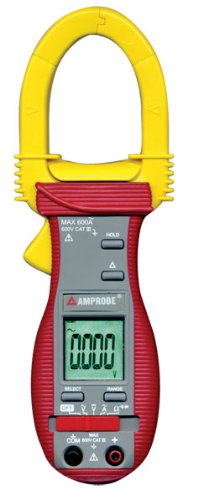
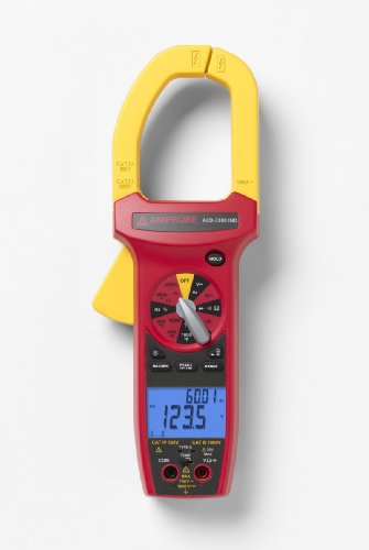
Clamp Meter

Our enterprise summarize many years sense of production and maintenance of Earth station Antenna and combined with the feedback of many customers from all over the world to create the daily inspection manual. We hope this manual can help the antenna users.

1. covering Maintenance

Check the perfect paint covering and electroplating surface, as well as fixed structure. First rub the rust spot on the electroplating covering by metal wire brush or polisher paper, and then coat a layer of zinc-rich coating or a layer of rust inhibitor which will not need the perfect clearance of the rust.

The user should mend it even if only a petite of the stop peeling or color fading, or it will come to be more and more serious. And the user must accord with the antenna builder regulation for the paint covering and coating specification, because the wrong coating method will influence the signals accept. For example, the dark-colored antenna reflector surfaces can absorb easily, and so it can give rise to high temperature, which can cause the signal distortion. Too much lead paint can make the signals loss by attenuation or scattering.

2. Antenna Fasteners

The nuts, bolts, rivets and other fasteners in the premise will be affected by atmospheric effect or internal corrosion. Regardless of any corrosive components and the error premise will be found in the disposition maintenance. At this time the users should tighten the loosen nuts and replace the lost, rust and corrosive components.

With the American community for Testing and Materials fabricate A325 or other occasions of conflict components, the user must replace the loosen or corrosive components, because in the process of re-tightening it will make the fasteners get the reuse term. Also the corrosive A325 metal parts should be substituted not be tightened.

Often there are pins inserting in the pivots of the adjustable antenna bracket. Check if the activities of these jointing are flexible, and lubricate the oil by a grease-gun with oil jet. If the antenna rotates not flexibly, the user should replace the pin.

Check the metal fasteners on the antenna reflector and back structure. Except American community for Testing and Materials fabricate A325 must be replace, the user can tighten the loosen parts. The lost, rust and corrosive fasteners should be replaced. These check processes are also favorable for the operational platform when assembling the antenna, as well as assisting the reflector and reflector support.

3. Ground

No matter how high the buildings, the antenna and bracket should be grounded to preclude the lightning strikes. inspect if the mechanical of grounding ideas and no mechanical association are connected.

Analyze if the grounding association is connected by the earth loop impedance instrument. According to the test results the user can decree the cost of the excavating work. Check if the mechanical grounding parts are rust, corrosive or loosen. Replace the rust and corrosive fasteners so as to limit the inductance value.

Unload the grounding sharp dogleg head on the antenna or bracket. According to the test results decree whether adopt auxiliary grounding measures.

On the place which can use the step auto-tracking device, check whether the pedal is level by a longitude and latitude stadia. If the pedal is not level, it can influence the antenna position calculation. Adjust the level nut under the base plate to make the antenna keep level.

If the anchor bolts preclude to adjust the pedal level, adjust it while fixing the antenna. After adjusting, check if the cement sealing of the antenna foundation and anchor bolts crush and shift. If it is damaged, even a little, also should be repaired. After adjusting, the controller should be programmed again.

If some devices are mounted in the antenna box which is on the back of the reflector, check if there is accumulated water or a large whole of termite or rodent infested in the box. mend or seal the crack, even if it is little. If the user do not care about it, ants, mice and other animals will cause improbable losses.

4.Cable and connector

Intermediate premise link cable transmits the signal between the antenna and computer room. Check if these cables are damaged. If there is something wrong with insertion loss, the user should test and check whether the cables need to be substituted or be repaired.

When repairing the cables, the user can splice them in the new position, but it can cause some signals attenuation. With Time Domain Reflector check the position of the broken line. With a voltage meter check all the cables and connectors of the electrical properties and connectivity.

The coaxial cable with a bend head in excess of the minimum bend radius should be tested. After testing if it does not comply with the cable specification, it should be replaced.

Ensure the I F L cable and other cable sustain and routing (positioning and bending radius) accord with the builder technical requirements. Replace the lost, rust and corrosive backup supports. When supporting I F L cables, it is good to use stainless steel cable link or cable clamp than the plastic rope. Stainless steel link should be used to fix the elliptical waveguide. inspect the cable builder recommendations.

If the stainless steel link or clip is not useful, and the cable builder have not specified any stainless steel link or clip, in this case the user can only use black nylon rope, the white or bright-colored rope is easy to be fragile in the sun. The user should always check the cable rope, because the nylon rope is easy to be loosen than stainless steel clip.

Check the I F L connectors and association parts. Replace the connectors which appear fracture line, line antihypertensive or other problems. If I F L cables come from the catheter, the user should check the catheter and other connectors. Check if the catheter input is strict, if there is accumulated water in the catheter, the water will freeze, which will squeeze the cable broken.

Check the feed combiner flexible elliptic waveguide line, if it is damaged, replaces it. If the ideas inflation pressure is not enough, corrosion can change the signal-to-noise ratio to influence the signal or cause the antenna stop working.

5. Shutdown Maintenance

Some maintenance work should be done when the antenna do not stop working, but most of the maintenance work need to be done after the antenna stop working. For example, when animated the antenna or cut down I F L line, the user must shutdown the antenna. First check the antenna azimuth and elevation bracket. Look if there is some fracture and hardening phenomenon for the security cover of the sustain bracket, if need, replace it.

For the motorized antenna or the antenna which points to a Satellite for a long time, sometimes those antennas also need to be moved. This step can be determined as part work of daily check in each year. Have other regulation. When doing the maintenance, According to the maintenance duration table of Ant our enterprise clear the sustain screw, and lubricate the oil.

If the user finds the sustain bar moved on one position and was wear, it should be adjusted. When rotating the antenna, ensure that mechanical limit switch can stop after antenna motor finishes the planed journey. The limit switch malfunction can make the antenna rotate continuously until it will be damaged or hit with other objects.

Check the operational maintenance of the Antenna Manufacturer,note that the extra requirements and propose when to lubricate the oil or when to inject the oil for the azimuth, elevation, polarization and other motors. Antenna motor wire box should be dust-free and moisture-proof and all the association should be fixed. If due to improper maintenance of the equipment, our enterprise will not be responsible for warranty.

6.Maintenance Record

Keep a maintenance record. At the starting of installing the antenna, leave a description with date and photos. Then voice once, keep a description once, so as to keep a perfect antenna ideas record.

In the antenna valid life keep a description of antenna pattern so as to find the phenomenon of the ideas signal dropping.

If it is required to shut down the antenna and do the maintenance, you should good arrange the maintenance work when the antenna does not work or within one hour at off-peak period. If the antenna can not stop work, exchange this antenna work to other temporary earth station antenna.

7. About our company

Our enterprise is a global victualer of communications systems equipment and services. Major markets are earth station antennas - which includes Satellite transportation antennas, receive only antennas, flyaway antennas.

For supplementary information, please send an email to us.

The Maintenance of Earth station Antenna

Friends Link : rockwell tools blog reviews video games Store

Wednesday, August 17, 2011

Home Power Generator scheme - Measuring Voltage Using the Volt Function of the Multi-Meter

Today, let's use the volts function on our multi-meter in order to portion voltage. Alternative vigor resources sometimes requires circuits you may not be well-known with. Don't take chances. vigor solutions are in your hands.

First, let's set our multi-meter to the highest range we have in case,granted for. Lots of times we will find that the voltage we have to portion is unknown. So why do we start out with the highest range possible? Because we want to be particular to not damage the machine and so set our machine to portion the highest range possible. We can all the time move down to a lower range. Electricity can be dangerous. To us as well as our machine.

Clamp Meter

The meter (not to mention us) cannot be damaged if we have set it too high. We will naturally note that we must move it down.

For example, if we set our meter to a 50 volt range and then plug into a household circuit of 120 volts, we could damage our machine (or us). So here's the point: all the time start high, and work down to the lowest range to be safe.

Next, place the black probe into the "Com" or "-" jack.
Then we will insert the red probe into the "V" or "+".

Now find your voltage scale. You may have more than one with dissimilar maximum values. You have a selector knob with which to resolve the voltage scale that you want to read. Look at this so you will understand what I am saying. With the range chosen the selector will resolve which scales of the voltage scales you will read. Unlike the Ohm scales we discussed the other day, the voltage scales are linear. It is definite in any place along its length. As you look at this you will be able to see that reading twenty volts on the 50 volt scale would be easier than the same twenty volts on the two hundred and fifty volt scale.

Let's test a base electrical outlet. If you are in the United States, you will probably find outlets with either 120 volts or even 240 volts. If not, the estimate might vary considerably.

Let's walk over to one of our typical American 120 volt outlets. Push the black probe into one of the right electrical slots. It should almost "connect" in the slot like a plug would. The relationship will grip it. Next push the red probe into the other slot. Check you meter now and you should be able to read a estimate almost exactly one hundred and twenty volts.

Now take off the probes and and rotate your selector now to the lowest range potential Greater than the voltage we just registered. Now reinsert the probes and you might find in any place between one hundred and ten to maybe one hundred and twenty five volts. See?

The range of the meter is important to accumulate any definite measurements. If your pointer did not move it is potential that you had the machine set on Dc instead of Ac. The Ac and the Dc are not compatible. It must be set correctly. Failure to do this could cause a Deadly mistake. all the time watch what you are doing. Be sure to try both modes if the pointer does not move. all the time check high.

Here's an important advice for safety: whenever possible, try to connect one of the probes so that it will not be required for you to hold both while development the test. safety first. Time is a secondary matter.

Some meters have accessories that might comprise things like alligator clips or any type of electrical clamp that allows you to minimize your contact with the electrical circuit. anything that reduces your contact with the circuit will also sacrifice the chances of sustaining burns or any other injuries.

The looming vigor transition will require you to take electronics into your own hands in ways that you might never have considered.

Your families depend on you. Do the right thing. But do it!

And do it Safe!!

Home Power Generator scheme - Measuring Voltage Using the Volt Function of the Multi-Meter

Visit : video games Store rockwellrk 9000 jawhorse rockwell tools blog reviews

Monday, August 15, 2011

Woodworking is a Fun Hobby to Have

Woodworking is a popular pastime of many. In the beginning it may seem like you need to make a huge speculation in tools. This is a misconception. Actually, most of the tools achieve similar tasks so you can save money by just getting the basics. Begin woodworking without spending a ton of money.

There are some easy woodworking tools you should have. Chisels are a must have. Quest for ones that are sturdy sufficient to stand up to a good deal of work. Rockler Chisels are a great, low cost choice. Buy chisels that range in size from ½ to 2 inches. Use chisels with mallets or hands.

Clamp Meter

Clamps can be found in a amount of separate sizes and are instrumental in a range of gluing endeavors. They are also rather cheap so there is no need to do major agreement shopping with it comes to clamps. When you see them you should get them. Don't spend your time visiting hardware store after hardware store searching for discounts.

Measurements are key in woodworking and squares are the best tools to use. Framing squares are astonishing to use when construction positive pieces of furniture. It is best to have squares that have both meters and inches on them. That way you will not have to translate instructions. A combination quadrilateral is a astonishing tool to have on hand. It is one of the best ways to portion 45 and 90 degree angles.

Drills with and without cords are available. The corded range of drills are handy and they tend to be rather cheap. When choosing drills, look for positive features. Good features to Quest for are reverse changeable speed controls and added tool to enhance the drill. Cordless drills generally have higher voltage batteries and they can be expensed easily. separate drill bits will usually come with anything drill you purchase.

Steel or wood hand planes are primary to have. Rough shaping is typically performed by a jack plane which can be found in twelve to fifteen inches. Block planes are good to have when a trim needs to be done.

While good deals on tools may be nice on your wallet initially they may come back to haunt you. If you buy the cheapest tools you may find yourself replacing them on a quarterly basis. It is best to wait until you are bale to buy decent tools. This will save money in the long run.

Check out the Internet for tools that are low priced but of good quality. Rigid, Sears, Rockler and Hitachi tools are all great brands to buy from. Buy high quality tools and handle them with care. Be particular to properly store them and fix them when they are in need.

Woodworking is a Fun Hobby to Have

Tags : rockwell tools blog reviews Motorcycle Store video games Store

Saturday, August 13, 2011

Power Windows Not Working, Off Track - "How To" Car fix Tips

Power windows not working in a car can be caused by several things. The most common cause is a bad power window's motor, the switch could be faulty or the regulator could be binding or the cable could be off one of the pulleys. Rarely, windows may just be Stuck in the weather stripping (called a run) and need to be freed up and the guides lubricated with silicone spray. As a scholar auto technician, I've repaired authentically hundreds of power windows in nearly all makes of cars over the years. In this how to record I'll let you in on some things to look for when diagnosing power windows not working. Ninety percent of the time, these type of problems can be diagnosed in less than sixty seconds! 

Stops Working 

Clamp Meter

If the glass moves a few inches and stops, then the motor is allowed time to cool down and will again move a few inches; the power motor will need to be replaced. If there is no sound coming from the motor, it may not be getting power or the motor itself may have an open circuit. Checking for power to the window's motor commonly requires removing the door panel to access the wiring. After access to the power window wiring is gained, a test light or meter can be used to see if it is getting power and ground. I've learned over the years a short cut that saves the hassle of removing the door panel for testing the motor. Most of the time when checking this problem, just turn the headlights and interior lights on; look for a miniature dimming of the interior or dash lights when the power window switch is pushed. If a miniature flicker or dimming of the interior lights occur, this indicates that the switch is functional and the motor is bad. Try this with one of the power windows that is working to gauge the affect on the interior lights. If there is no change in the radiance of the interior lights when trying this with the inoperative window, the switch could be bad.

Appears to Be Off track or is Binding  

Windows don't commonly just go off track (the regulator fails causing it to move out of the general position). If the window appears to be off track, the regulator has most likely failed. Window regulators whether use metal gears (which rarely fail) or they use a cable and plastic pulley compose - which commonly fail. If the window has fallen, the regulator will most likely need to be replaced. If the glass is cocked unevenly and is binding, the regulator has most likely came apart. The motor will be heard when pushing the switch in many cases but the window won't work correctly due to the failed regulator.

Diy Tips to Try

Sometimes electric contacts in the window switch can be worn, corroded or dirty. Try pushing  the switch with your finger hard and deliberately - if the window starts to work, the switch is the question and will most likely need to be replaced. After accessing the motor, try tapping on it with an object  (like a small wrench or a 3/8" extension) - if it temporarily works, the window motor will need to be replaced.

Power Windows Not Working, Off Track - "How To" Car fix Tips

Thanks To : video games Store uk games and toy store to buy

Thursday, August 11, 2011

Great Price Amprobe VPC-30 Voltage and Continuity Testers, LED Indicators only

Amprobe VPC-30 Voltage and Continuity Testers, LED Indicators only Review


Click To Buy Best Price from Amazon

Product Feature

  • Super-bright bi-Color LED's indicates safe and dangerous voltages (above 55VDC or 30VAC)
  • Auto hold feature - LED's stay illuminated for 10 sec retaining a reading after the tests are disconnected
  • Solenoid tester-like shaker to indicate AC voltage presence
  • Automatically turns ON and OFF for easy and quick measurements
  • Non-contact voltage detection and GFCI test feature for testing GFCI receptacles and breakers

Product Overview

Standard detachable test lead (black) for easy replacement with optional longer or specialized probe -- Automatically selects AC Voltage, DC Voltage or Continuity -- LED's indicate 10 levels of AC and DC Voltages::Volts (AC) 24, 48, 120, 208, 240, 277, 347, 480, 600, 1000 -- Volts (DC) 6, 12, 24, 36, 48, 60, 72, 110, 220, 380 -- Auto backlit LCD Digital Display for precise voltage measurements -- Continuity buzzer and Visual continuity indication (LED) -- Water and dust proof, IP65 design

Read More ...


Recommend : psp2 go Reviews video games Store uk games and toy store to buy

Tuesday, August 9, 2011

Great Price Amprobe ACDC-100 TRMS AC/DC Digital Clamp-On Meter

Amprobe ACDC-100 TRMS AC/DC Digital Clamp-On Meter Review


Click To Buy Best Price from Amazon

Product Feature

  • TRMS & Display Backlight (ACDC-100TRMS)
  • Auto & Manual Ranging
  • Relative Zero Mode
  • Auto Power Off
  • Capacitance to 3000 µF

Product Overview

Where accuracy, quality, and the newest technology meet. The Amprobe ACDC-100 offers superior AC/DC measurement capabilities, highest product quality and enhanced ergonomics with Amprobe's Red, Rubber, Ribs design. The ACDC-100 TRMS Version addresses needs of professionals who rely on performance and reliability.

Read More ...


Thanks To : rockwell tools blog reviews

Saturday, August 6, 2011

Great Price Amprobe ACD-14 Plus 600A Clamp-On Multimeter with Dual Display

Amprobe ACD-14 Plus 600A Clamp-On Multimeter with Dual Display Review


Click To Buy Best Price from Amazon

Product Feature

  • Dual Displays - Permits simultaneous reading of Amperage & Voltage
  • AC Current to 600A
  • New thin jaws, 5mm thinner than others to access tight measurement spaces
  • Micro Amps measurement for testing Flame Sensors
  • Battery Ok Test

Product Overview

The ACD-14 PLUS is the professionals' choice for both HVAC and Electrical applications due to its complete set of measuring features. Its dual displays allows viewing amperage and voltage simultaneously. The ACD-14 PLUS meter offers thinner jaws over standard clamp meters. Allowing access to tight measurement areas and still accommodating conductors up to 28 mm. Both meters also measure Capacitance and Frequency. Very versatile clamp multimeters to support all your daily measurement needs.

Read More ...


Thanks To : Motorcycle Store uk games and toy store to buy

Thursday, August 4, 2011

Check Out AC CURRENT CLAMP for $210.53

AC CURRENT CLAMP Review


Click To Buy Best Price from Amazon

Product Feature

  • Pair a current clamp with your scope or power quality meter to measure up to 400A AC
  • Specially designed to offer maximum utility in a compact shape
  • Take accurate current readings without breaking the circuit
  • Soft non-slippery overmold handle
  • Can be used with DMMs with optional PM9081/001 BNC/Banana adapter

Product Overview

Only current clamp available with CAT IV 600 V / CAT II 1000V safety rating makes them ideal companions for modern CAT IV rated meters. The i400s clamp has a BNC termination and two ranges with output levels of 10 mV/A and 1 mV/A that works with Fluke Scopemeters and Power Quality analyzers, such as the 43B. The i400s also has a 2.5-meter cable.

Read More ...


Related Products

Thanks To : Motorcycle Store

Tuesday, August 2, 2011

Check Out Fluke 80PK-18 Pipe Clamp Temperature Probe Kit for $275.99

Fluke 80PK-18 Pipe Clamp Temperature Probe Kit Review


Click To Buy Best Price from Amazon

Product Feature

  • Type-K thermocouple for fast temperature and superheat measurements of pipe surfaces
  • Durable patented ribbon sensor with protective cover when not in use
  • Measurement range is -20 to 300 Degree Fahrenheit (-29 to 149 Celsius)
  • For pipe diameters: 1/4 to 3/8-Inch (6 to 35 mm) and 1.25 to 2.5-Inch (32 mm to 64 mm)
  • Includes: 80PK-8 and 80PK-10 Pipe Clamp Temperature Probes

Product Overview

The 80PK-18 Pipe Clamp Temperature Probe kit combines the standard 80PK-8 pipe clamp with the larger sized 80PK-10 pipe clamp, to give you a full range of measurement sizes. The Type K, thermocouples clamp securely to pipes for fast temperature and superheat measurement. The included soft carrying case allows you to conveniently keep both clamps close by for any situation.

Read More ...


Related Products

See Also : Automobuy Store video games Store